

The fuel system has different functions, which are:
- storage, venting and scavenge,
- engine feed,
- APU feed,
- main and trim transfers,
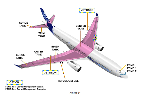
- refuel/defuel,
- jettison as an option,
- and the maintenance/test facilities.

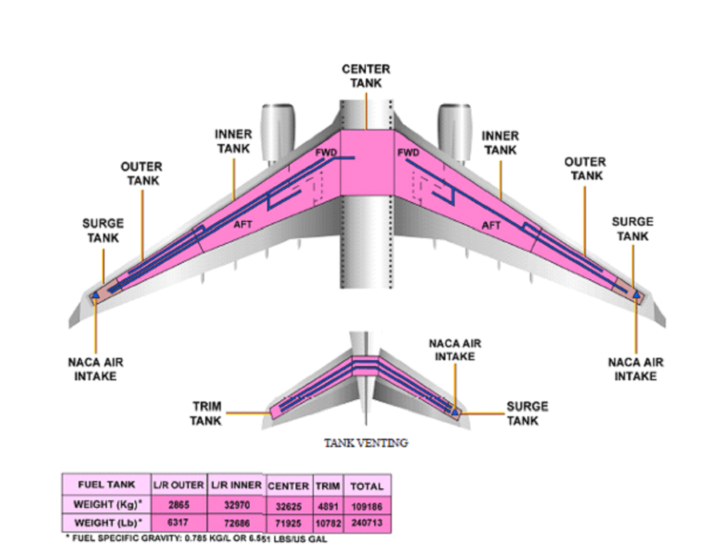
The fuel is stored in six tanks. In each wing, there are an outer and an inner tanks divided into two parts: the forward inner tank, and the aft inner tank. There also are a center tank, and a trim tank. Each inner tank section has one closed area called the collector cell, which is a reservoir for the booster pumps.
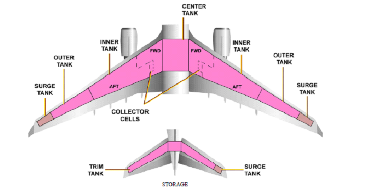
A dedicated jet pump is only used to fill the collector cell of the main booster pumps. A vent surge tank is installed outboard of each outer tank in the wing and on the RH side of the trim
tank. They vent the fuel tanks and collect fuel split from the tanks. Each tank has one or more water drain valves located at low points.
Two Fuel Control and Monitoring Computers (FCMCs) receive inputs from the different probes and sensors installed in the fuel tanks. The FCMCs transmit data to the ECAM and to the Refuel/Defuel panel. Each FCMC does the data monitoring and the calculation simultaneously, however one computer at a time achieves the control function (FCMC1
in normal condition).
Two high level sensors are installed in each tank. When high level is
sensed, the FCMC closes the related tank inlet valve. Low Level sensors are installed in each tank except in the outer tanks. They are used to
control fuel operations and to trigger low-level warnings. One overflow sensor is installed in each surge tank. If an overflow is sensed, the FCMC closes all inlet valves and the refuel isolation valve. In each fuel tank, the fuel quantities are measured from Fuel Quantity
Indication (FQI) probes, compensators and densitometers. Temperature sensors are installed in each tank for fuel temperature monitoring and ECAM display.
Source – Airbus