
SUCK-SQUEEZE-BANG-BLOW

More complex answer:

Let’s initially ignore the most common type of jet turbine engine in use today, the turbofan, and focus on the turbojet engine, which were used in the US Navy’s A-6 Intruder and F-4 Phantom II.

- (Typical single spool turbojet engine)
The turbofan and turbojet engines share a similar hot section and cold section, but the turbofan adds a larger diameter fan just forward of low pressure stage of the cold section. That’s the only major difference in design.
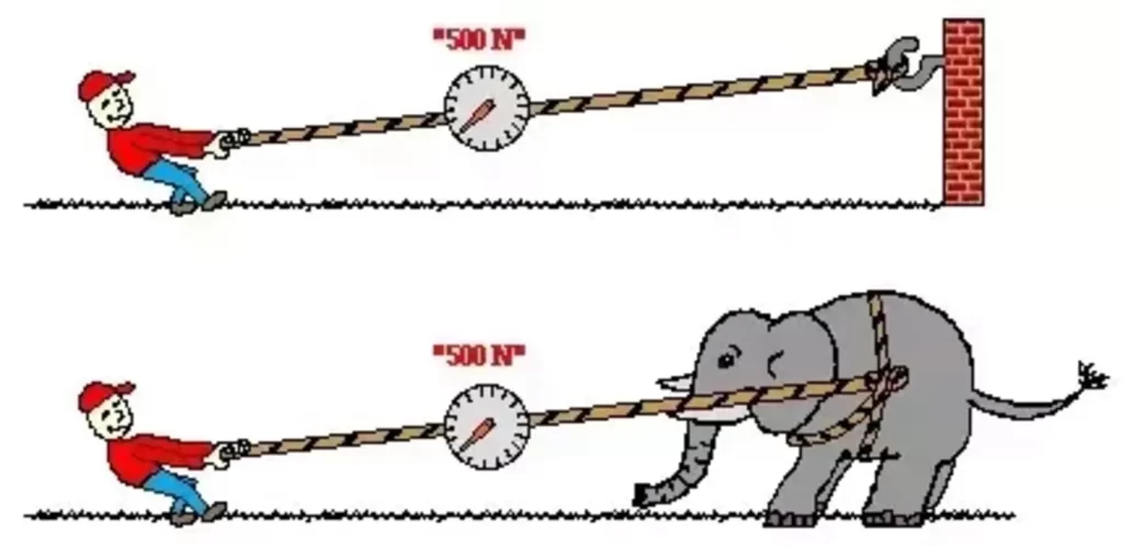
- The turbojet creates thrust by creating an action, and consequently a reaction. It increases the energy of the air that enters the engine before it exits out the exhaust nozzle by burning some type of hydrocarbon fuel, usually jet fuel. Newtons Third law of motion comes into play. Formally stated, Newton’s third law is: For every action, there is an equal and opposite reaction. The statement means that in every interaction, there is a pair of forces acting on the two interacting objects.

- (Newtons Third Law of Motion)
- The size of the forces on the first object equals the size of the force on the second object. In this case, the action is the jet engine increasing the pressure and velocity of the intake air, and moving it out the exhaust nozzle of the engine. The reaction is the “Thrust” acting on the engine to push it forward. Since the engine is mounted to the airplane, the airplane is propelled forward.
To offer an easily understood analogy, turn on a garden hose with the water valve fully open, and without a nozzle attached. It’s relatively easy to hold. Now turn off the water and attach a pressure washing nozzle tip. Turn the water back on. The hose will now be propelled backwards with a far greater force than before, by the action of the water being accelerated out the nozzle tip, and the resulting reaction. That’s thrust.
A turbojet or Turbofan engine increase the energy of the air entering the engine intake in several discrete steps:
First, ambient air is drawn into the rotating axial flow compressor via the intake and is compressed to a higher pressure before entering the combustion chamber. Typically a compressor has two sections, each one rotating independently. The forward compressor section is the low pressure compressor. The next compressor section is the high pressure compressor. It rotates on a separate, or split shaft from the forward low pressure compressor. Each turbine section is comprised of multiple rows of compressor blades, each row is referred to as a “stage”. The diameter of each stage gets successively smaller, as the air becomes more compressed as it transits through the compressor section. The engines depicted in the diagrams each have 14 rows of compressor blades, and are therefore called 14 stage compressors. The compressed air exiting the compressor is already very hot, and when atomized fuel is mixed with this air in the next section, the combustor or combustion section, it will auto-ignite.
A jet engine typically has a compression ratio similar to a Diesel engine, which is about 14 to 1.

- (Single spool axial flow compressor (top); Twin Spool axial flow compressor (bottom)
Next, the compressed air enters the burner section. Fuel is mixed with the compressed air and burns in the combustor or within the burner section. The burners can be an annular shaped burner (annual burner), a series of cans (can burner), or a combination of annular and cans (can annular burner).

- (Jet Engine Combustors or Butners)
Next, the high combustion products leave the combustor at high velocities and high pressure, and then expand through the turbine section where energy is extracted by the turbine blades, and this causes the turbine shaft to rotate at high speeds. This rotational energy is used to drive the compressors (and the fan in a turbofan engine).

- (Turbojet Engine Combustion or combustor section)
Typically the turbine section also has a high pressure turbine section that drives the high pressure compressor section, then a low pressure turbine section that drives the low pressure compressor section. (In a twin spool turbofan, the low pressure turbine also drives the Fan Section.

- (Twin spool Turbofan Engine diagram)
Both the high pressure and low pressure sections rotate independently of each other on independent twin spools, and therefore each spool turns at different RPM’s. These values are known as N1 ( Low pressure section), and N2 (High Pressure section). They are displayed as a percentage of their maximum values on the cockpit engine displays. In Rolls Royce engines such as the Trent 900, the fan section is driven by an additional 3rd independent spool turbine, located aft of the low pressure turbine, called Nf or N3. The Rolls Royce Engines are all triple spool turbofans. GE and Pratt &a Whitney only build twin spool turbofan Engines.

- (Rolls Royce Trent Triple Spool engine cutaway)
In the final stage, the turbine exit gases still contain considerable energy that is converted in the propelling nozzle to a high speed jet. This is the action. The thrust is the resultant reaction that propels the aircraft.
In a turbofan engine, the rotating fan blades also create the action and reaction that contribute to the engine total output thrust.

- (Exploded View: GE NX Jet Engine Turbofan (split spool engine)
In a pure turbojet engine, 100% of the engine thrust is a developed by the exhaust flume. In a turbofan engine such as a GE90 or a RR Trent, about 90% of the total engine thrust is developed by the fan.
Net thrust acting on the aircraft can be calculated empirically by measuring the total mass of the air and fuel going through the engine in pound units in a given time period, then multiplying that value by the speed of the Jet exhaust flume minus the speed of the aircraft.
Net Thrust = m(o) x (c – v)
m(0) = mass flow through engine
c = exhaust flume velocity
v = aircraft velocity
This calculation ignores ram drag and supersonic plume velocities to keep it simple. However, as the speed of the aircraft approaches the speed of the exhaust flume, net thrust drops to zero. Maximum thrust is developed when the aircraft is stationary.
Maximum propulsion efficiency is achieved when the speed of the aircraft and velocity of the exhaust flume are equal. This is why turbofans are more efficient at lower altitudes and lower aircraft speeds. Their exhaust flume velocities are closer to the operational speeds of most airliners than would be a turbojet engine.

- Jet Engine Propulsive efficiency (Np) (red line)
Np=2v / c + v
c= propulsive gas or jet flume velocity
v= aircraft velocity
This ignores cycle efficiency (Nc) which accounts for drag, coupling losses, etc., or the losses incurred by the engine in transferring the total input energy into energy output.
Author – Steve Bazer (Former Airbus A350 Captain at Delta Air Lines)