


“An indication of a hard landing on the main landing gear is a peak recorded vertical acceleration that exceeds 2.2 G (incremental 1.2 G). This vertical accelerometer data must be measured by the flight data recorder accelerometer at a data sampling rate of at least sixteen (16) samples per second. This vertical acceleration G-level threshold is valid for a conventional landing with impact with no more than two (2) degrees of airplane roll, main landing gear touchdown first and normal rotation onto the nose gear. For a hard landing that is a hard nose landing or is accompanied by more than two (2) degrees of roll at the time of main landing gear impact, the recorded peak acceleration can be significantly less than the 2.2 G, but a hard landing inspection may still be necessary.”
What action needs to be taken?
When a hard landing has occurred or is suspected by the flight crew or cabin staff, Boeing recommend the hard landing inspection be performed.
The hard landing inspection is conducted in two phases:
Phase I. A close visual inspection of various structural components, especially those most vulnerable to damage, to determine whether further inspections are warranted. Phase I inspections are kept as simple as possible with minimal access and disassembly requirements.
During the phase I inspections of the main landing gear, operators should check for shock strut leakage and examine the inside diameter of the fuse pins of the drag strut and the outboard end of the main landing gear beam for distortion. This involves checking for visible damage to the specific component without removing it. Operators also should examine the main landing gear beam to the inboard rear spar stabilizing link for damage to the link or the crank shafting of the forward and aft attach bolts. This is accomplished by loosening the nut on the stabilizing link bolt and turning the bolt to determine whether it is deformed or crank-shafted. Damage at this location will warrant further action during phase II inspections; specifically, the trunnion link should be removed in accordance with the AMM and the forward trunnion fuse bolt inspected. On the outboard attach fuse pin for the main landing gear beam, the retention bolt should be removed and the pin rotated to check for crank shafting.
Phase 2. A second phase of inspections is conducted if any damage is found during phase I.
During phase II inspections of the main and nose landing gear, operators should ensure proper hydraulic fluid levels are in the shock struts by performing a two-point service check, or by completely servicing the shock struts in accordance with the AMM. Operators also should remove the landing gear inner cylinders if shock strut servicing was found to be incorrect or if both a hard and a high-drag-load or side-load landing occurred at the same time. The barrel of the inner cylinders and axles also should be dimensionally checked for distortion or bending and examined for cracking.
Airline technical and operational staff may be consulted following phase I and II inspections, depending on inspection findings. Boeing is often requested to provide technical assistance during such reviews.
Additional information can be found in the Aircraft Maintenance Manual, Chapter 05, Section 05-51, Hard Landing or High Drag/Side Load Landing, and in the AERO magazine, Issue 14, there is an article titled Updates to 737 Conditional Maintenance Inspection Procedures dated April 2001.
Other types of non-normal landings requiring inspections
These include high-drag-load, and side-load landings, as well as off-runway excursions.
Off-runway excursions occur either on hard, even surfaces that do not create higher-than-normal loads or on uneven surfaces with depressions and obstructions that also may include soft and muddy conditions. The latter situation can create high vertical, high drag, and side loads when the gear goes over rough terrain or when the airplane stops suddenly in soft terrain.
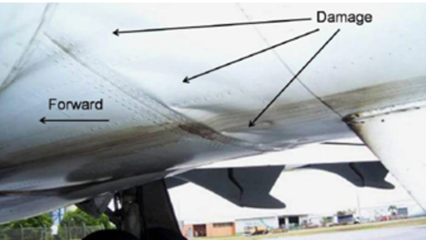
Travel onto surfaces with depressions or obstructions will generally require close inspection of all fuse pins during the two-phased inspection process outlined in the AMM. The gear then may be removed for closer inspection depending on flight crew judgment, FDR/QAR data review, consultation between the operator and technical experts, or the discovery of any structural anomalies. In addition to fuse pin deformations, axle and truck deformations may be discovered during close inspection of the gear. When an airplane goes into soft or wet turf or the gear picks up debris (fig. 5), in addition to high-drag-load conditional inspections, the wheel and tire assemblies should be replaced because water or dirt may have contaminated the wheel bearings. Also, the wheel speed transducers should be removed and inspected; brakes should be washed, examined for obvious damage, and operationally checked; and the entire gear should be cleaned of debris, especially under the axle sleeves, and relubricated.
In one instance, an axle fracture was attributed to moisture and mud under the axle sleeve following an off-runway excursion. According to the maintenance records, no inspection or cleaning was done, and the contamination resulted in corrosion and crack initiation.
INFORMATION PART 02
The inspection procedure for heavy landing is laid on ATA chapter 05. Usually on 05-50-xxx unscheduled maintenance checks.
An aircraft may land overweight in an emergency. also known as heavy landing. The landing gear is designed to withstand landing at a particular weight and vertical decent velocity. If either one of these parameter is exceeded, it is probably that some primary or secondary damage be found on the fuselage upper or lower skin. In all cases of suspected heavy landings, the flight crew should be consulted for details of aircraft weight, fuel distribution and landing conditions.
It is difficult to confine the possible damage to certain areas. The following areas are usually inspected for damage.

Landing Gear
- Examine tyres for excessive creep, flats, bulges, pressure, loss etc.,
- Check wheels, brakes, struts, axles and stays for damage, distortion and fluid leakage.
- Examine landing gear attachments and vicinity for damage distortion and movement of rivets, bolts etc.,
- Check shock struts for fluid leakage, normal extension and carry out nose-¬wheel tests as per approved maintenance manual.
- Examine the trunnion links, torsion links, truck beams, side struts and truck position mechanism.
Mainplanes
- Examine upper and lower surfaces for signs of wrinkling, pulled rivets, cracks and movement at joints.
- Check for fuel leakage from integral tanks.
- Check the operation of flying controls and lift augmentation devices.
- Check balance weights and mountings, wing spars for cracks and distortion.
Fuselage
- Check the fuselage skin and supporting structure for wrinkling, cracks and distortion.
- Check bulkheads for distortion and cracks.
- Check that the inertia switches for fire extinguishers, emergency lights have not tripped.
- Check security of passenger service panels and in particular that emergency oxygen systems have not been activated.
- Check pipes, tubes, service and instrument panels for damage.
- Check for fit of doors and condition of cargo restraint system.
- Check gyroscopic instruments for erection time, precession and unusual noises.
Engines
- Examine engine controls and rotating assemblies for full and free movement.
- Check engine mountings and cowlings for damage and cracks.
- Check oil system filters and leaks.
- Check propeller attachments and counterweight installations. Provided that no major structural distortion has been found, engine runs should be carried out in accordance with the relevant maintenance manual.
Boeing has intentionally not published specific values for either rate of descent or vertical acceleration which quantify a hard landing. This position was established after careful review of available flight/aids recorder data and flight test experience.
Accelerations registered on flight data recorders are not considered to be adequate indicators for hard landings for several reasons. Accelerometers measure G forces at their installed location only. There is no way of knowing whether the forces are a minimum, a maximum or some intermediate value due to the data sample rates. These devices can provide reliable acceleration data during inflight maneuvers where accelerations are steady or slowly varying. However, Boeing flight tests have shown that recorded acceleration data could be a significantly inaccurate indictor of a hard landing. This results from the system response during the short time when the wheels are contacting the runway. During this interval the recorded vertical acceleration component can become highly erratic. In those cases where apparently valid data is readable, data sampling rates or recording time intervals are such that the peak value is usually not discernible.
Additionally, several accelerometers placed throughout the airplane have revealed significant variations in both time and magnitude of G forces (structural loads) due to the airplanes weight, CG, motion (sink rate, forward and side velocity, roll, pitch and yaw angles and rates), external forces (gust loads, ground effect, runway contact loads) and structural dynamics (vibrations, harmonics). Because of the number of complex factors which must be analytically combined and correlated to an equivalent G force factor, Boeing has concluded that a reliable method is impractical. Quoting a G level low enough to assure the airplane has exceeded the design sink speed, the appropriate criteria would lead to frequent and unnecessary inspections. Quoting a medium or high G level for the inspection threshold would result in some high sink speed occurrences without an inspection.
Boeing believes pilot judgment and reports describing the landing remain the best source of information for ascertaining if a hard landing has occurred. Pilots ordinarily land the airplane well within the allowable limits and become accustomed to the sensation. Translation of service experience reports indicate that airplane flight and cabin staff typically report a hard landing when sink rates approach 4 feet per second (240fpm). All Boeing model airplanes have been designed for a 10 feet per second (600fpm) sink rate at the maximum designed landing weight and 6 feet per second (360fpm) at the maximum designed takeoff weight. These values are considered when designing both the main landing gear and nose landing gear assemblies as well as the wing and fuselage support structure.
Note that if the acceleration values are recorded during a hard nose landing or accompanied by more than 2 deg of roll at the time of main landing gear impact, a hard landing may be experienced at significantly smaller vertical acceleration values.